Subpage:pipeline Distortion
design 2024, PCB build version 2025
Introduction:
This simple circuit provides flexible and dynamic signal distortion as a sound effect for synthesizers
and gitars. A series chain of saturating amplifiers is used with adjustable output summation that allows
many kinds of overdrive curves. In addition, an optional low-frequency modulator creates dynamically
changing distortion effects.
Movie explaining the basics with oscilloscope-waveforms and sounds:
YouTube link for the basics
Movie showing the PCB build version with oscilloscope-waveforms and sounds:
YouTube link for the build version
The Pipeline Distortion concept:
If you cascade identical amplifiers, then an increasing input signal will first saturate the last amp,
then the amp before that, and so on.
Now if you take the output of each amplifier and send this to an output summator,
using adjustable gain and sign, you can create all kinds of overload behaviour.
Concept implementation:
To prevent getting a too complex user interface, I simplified things a bit.
Four amplifiers are used and each has a 3-position switch that allows the user to add-ignore-subtract
the signal from it. In the circuit shown, you could also use 100k potentiometers instead of
these switches if you want more adjustment possibilities.
The user interface of the basic version could then look like this:
Circuit implementation (see basic circuit diagram below):
To keep things simple and cheap I used one chip (less than 1Euro) that contains six amplifiers:
the hex CMOS inverter 4049UB (UB=unbuffered version). These unbuffered logic gates are actually
high-gain inverting amplifiers that can very well be used for analog purposes.
This chip is widely available and active in production, even in DIL-package.
Adding negative feedback using resistors sets the gain, just like you would do with an opamp.
Cascading then four of these amplifiers gives a circuit (the pipeline) where a rising input
level sequentially saturates: amp4, amp4+3, amp 4+3+2, amp 4+3+2+1.
The gain of amp1 (U1A) is made variable, being the input gain. Gain of amps 2,3,4 was chosen to be fixed 3V/V.
To allow both addition and subtraction of these four amp signals, each amp signal can be routed via amp
number 5 (U1E, summing analog inverter) or can be directly send to Amp 6(U1F), the overall summing amp and
the output variable-gain stage.
Basic circuit of the distortion (without modulator):
If saturation occurs symmetric, you create odd harmonics, so a potmeter labelled "symmetry" has been
added that allows the user to tune in asymmetry and thereby have more even harmonics.
To make the effect more lively, a low frequency oscillator (LFO) is added that can slowly sweep
the symmetry setting. The LFO has a "depth" and a "rate" potmeter, the resulting modulation signal
is made visible with a LED. A dual CMOS opamp chip makes the LFO, see full circuit diagram.
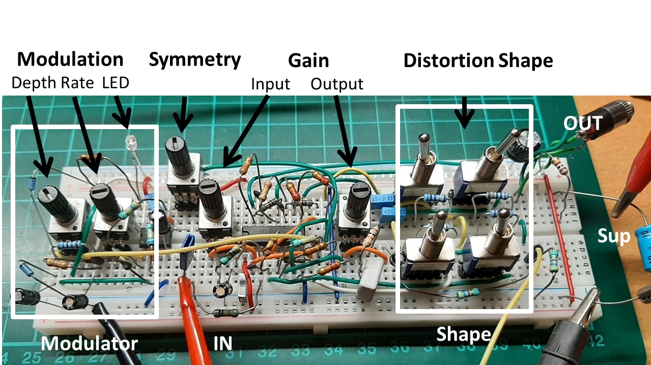
prototype circuit, including modulator:
The circuit runs best on a supply voltage of 4 to 5V and draws only a few mA so it is
feasible to use a battery supply.
The prototype breadboard-circuit, and proposed user interface:
-------------------------------------------------------------------------------------------------------------------------------------------
The PCB based build version (black PCB is also front-panel):
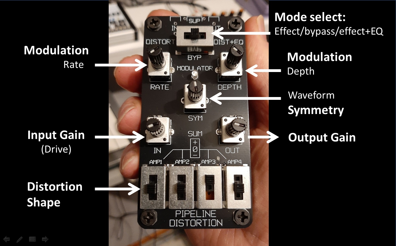
Circuit additions to the basic diagram: odd/even harmonics control(1), modulator(2) and equalizer(3):
1-If saturation occurs symmetric, you create odd harmonics, so a potmeter labelled "symmetry" has been
added that allows the user to also tune in asymmetry and thereby have more even harmonics.
2-To make the effect more lively, a low frequency oscillator (LFO) is added that can slowly sweep
the symmetry setting. The LFO has a "depth" and a "rate" potmeter, the resulting modulation signal, both depth and rate, is made visible with a LED.
A dual CMOS opamp chip makes the LFO, see full circuit diagram.
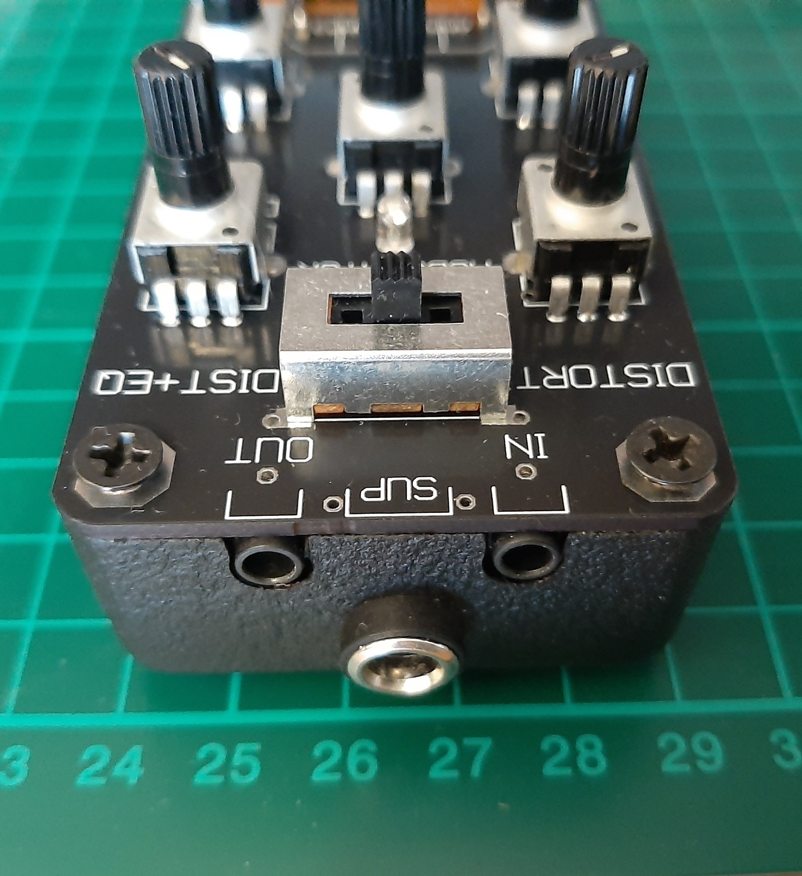
3-Using the same a 3-position switch for "Bypass" or "Distortion" selection I decided to make the 3rd position "Distortion and Equaliser" adding a simple fixed bass and treble boost filter.
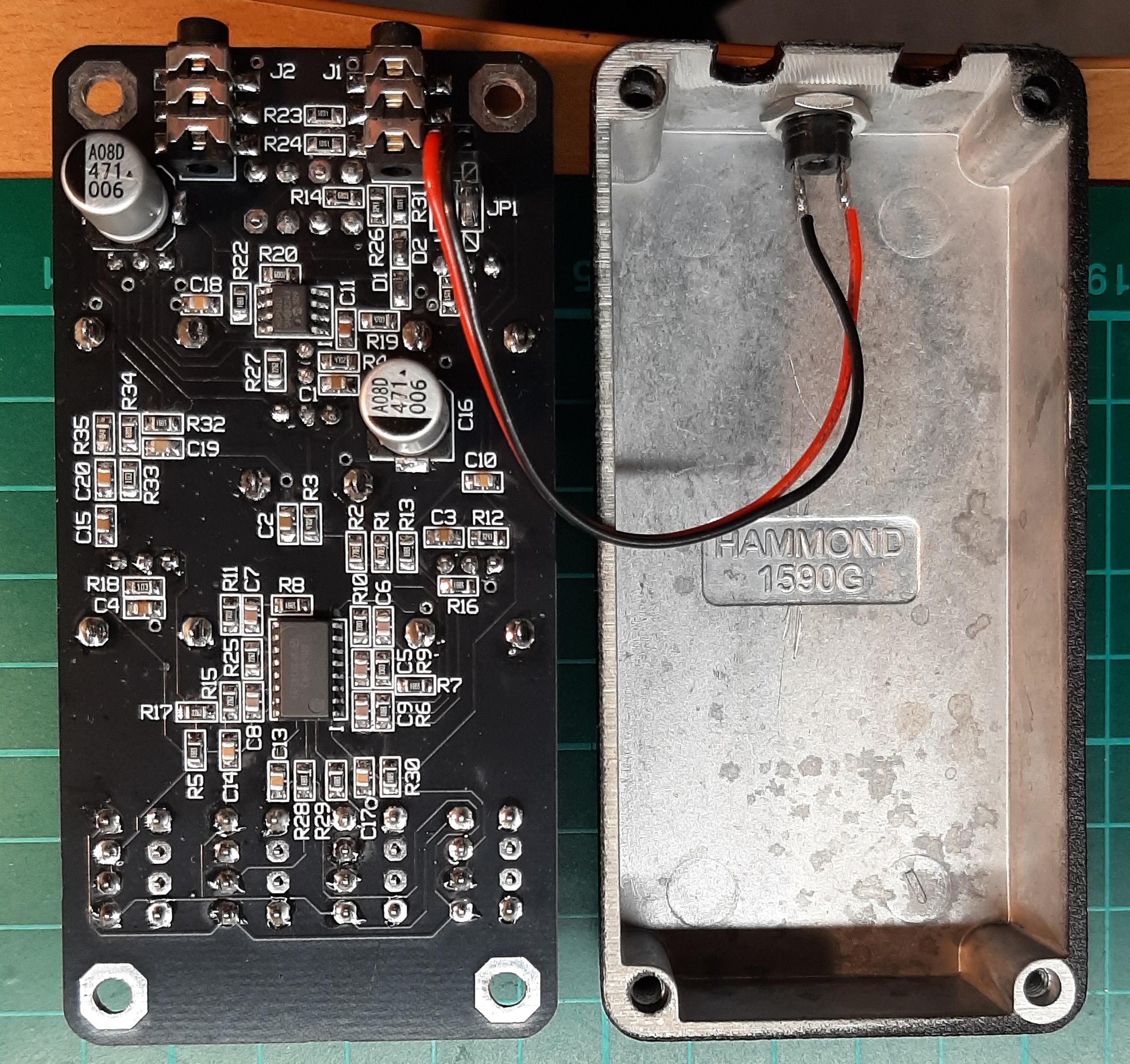
The backside and inside of the box:
PCB circuit, including modulator and switchable equalizer:
DIY information on the PCB build version:
detailled information on the used components
PCB Gerber files
PCB component placing info (not tested)
note: I soldered the components by hand