SubSub page: Filtertype MonoVoks (inspired by PoliVoks concept)
designs started 2014, latest version 2021

Introduction:
The Russian synth PoliVoks (1982) has a filter circuit that uses no capacitors or inductors but exploits the behaviour of a special type of opamp.
These opamps have an additional pin that allows you to set the supply current from mA down to the uA range. This also changes bandwidth and slew rate. The PoliVoks filter is build with 2 of these type of opamps.
Here is the original circuit, A2 and A3 create the filter, A1 is doing the current control on both:


I found a modern opamp with this control pin and comparable behaviour. After quite some tweaking I designed a new cicuit with a complete VCF using only 1 opamp, running on a single 5V supply. This specific opamp (TS271, not TLC271!) can be used as a voltage controlled lowpass filter from max 100kHz to 10Hz by sweeping it's supply current via the control pin. For these applications I limited the range to 15kHz-30Hz.
In addition a voltage controlled Q can be realised by making use of the asymetric output stage.

I made several VCF designs using this opamp. The monoVoks2 filter has a switchable lowpass/highpass function, all others are lowpass.
Latest VCF version to be used in the upcoming MonoVoks4 (expected Oct 2021):

open document describing all the details
Soundexample "songs"
Synth MonoVoks4 breadboardversion (proto) with this filter playing the synthsound:
BassSub Osc : changing Q
PortamentoBass : Glide
Wobble : LFO on filtersweep

Clean comparison track, static saw in (right channel) filter out (left channel) Q-increase up to oscillation: "FilterLeft-InputRight"

Explanation on Q:
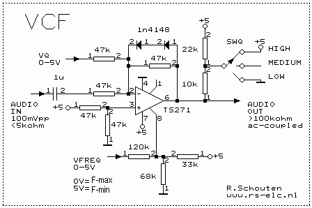
Inside part of the opamp:

For testing the TS271, the opamp was set as an inverting amplifier, gain 1V/V (see circuit diagram below). When the opamp output is supplying positive current, doing current sourcing, FET T15 delivers via it's source (=low impedance) but when the opamp has to do current sinking FET T16 becomes conducting via it's drain (=high impedance).
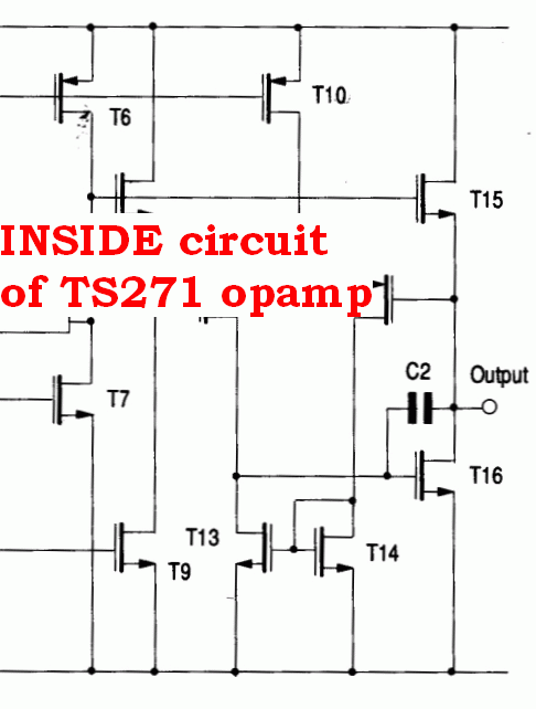
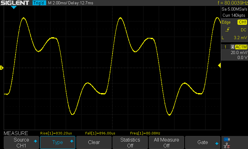
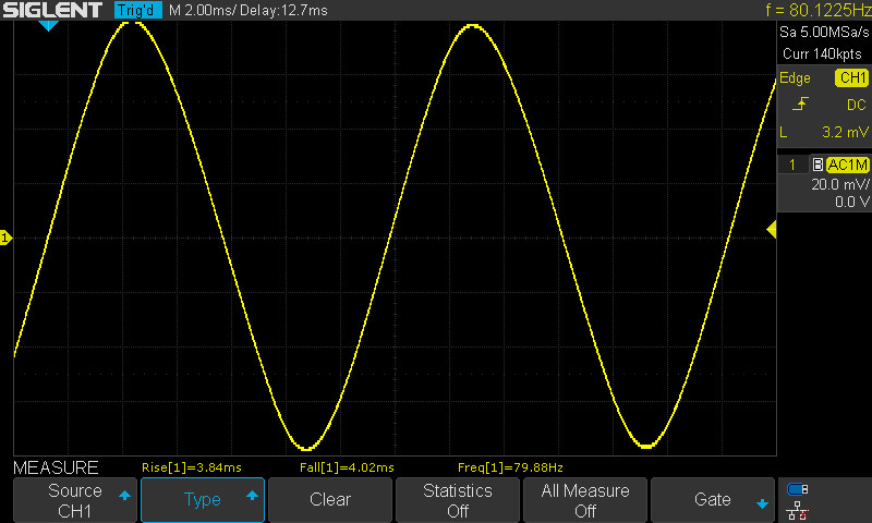
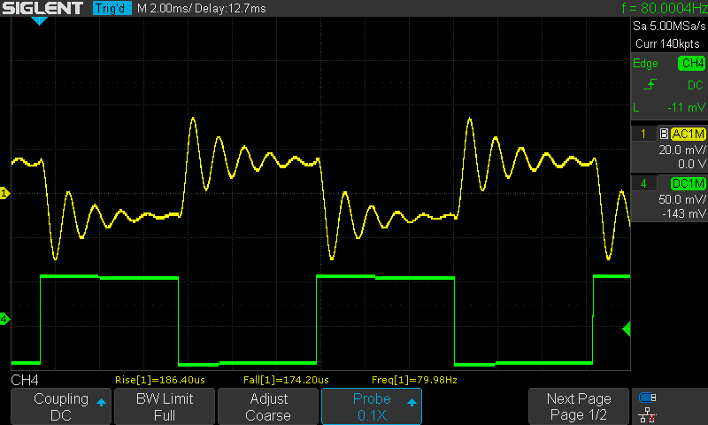
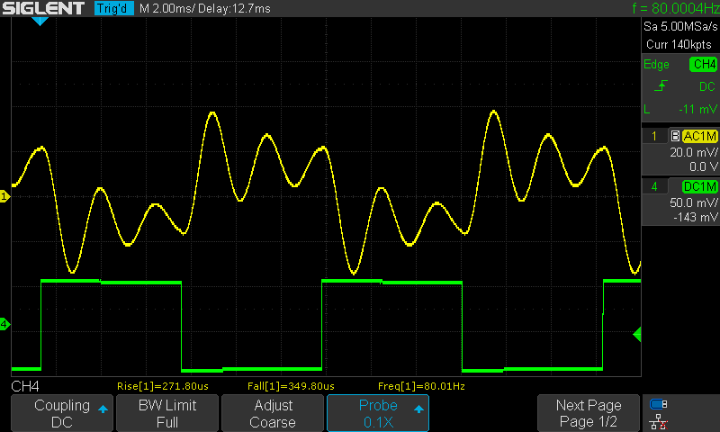
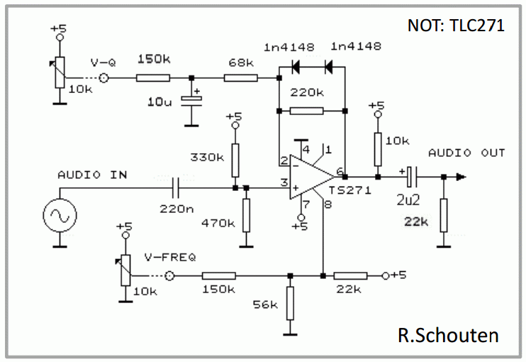
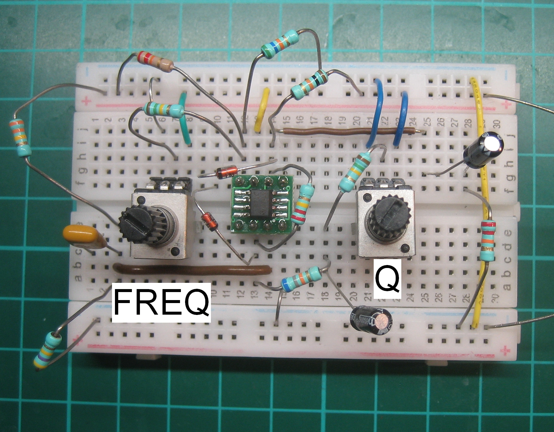
By dc-shifting the output stage and loading it with resistors you can go from a damped filter (T15 doing the work) to a peaking, resonant filter (T16 doing the work). Further higher peaking (higher Q) can be accomplished by lowering the feedback resistance to increase loopgain and thereby degrade damping (see diodes in circuit below).

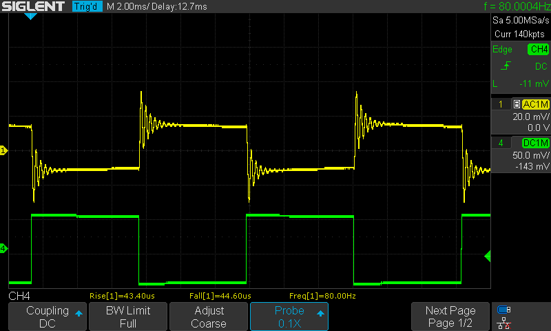
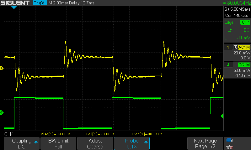
I did found this behaviour on each TS271 I tested (approx 15) both with DIL (older model) and SOIC housings. Note that I also found that the TLC271 could not be used this way, only the TS271 can be used.

Here are some measured scope traces of a filter frequency sweep with damped response, input is 80Hz square wave:

Scope traces of a filter frequency sweeps with medium peaking response created by dc-shift, input is 80Hz square wave:

Scope traces of a filter frequency sweeps with high peaking response, using dc-shift and feedbackchange, input (green) is 80Hz square wave:

This is the first VCF circuit I designed with the TS271 that allows for damped response, medium peaking, high peaking up to controlled oscillation:

The diodes in this circuit should be seen as a variable, current controlled, resistor with Rdiode=25k/I[uA]. This increases the Q by lowering the loopgain when VQ goes below approx. 2V. VFREQ sets the filter frequency from 20Hz to >20kHz using a single control voltage (PWM-DAC from microprocessor).
The switch SWQ can be implemented by toggling a microprocessorpin between out-high/input/out-low.
Together with VQ (PWM-DAC) this could be combined in software to have one control potmeter (ADC-in or MIDIcontroller) to set all Q-values.
The filtercircuits in the MonoVoks1 and MonoVoks2 are based on this with minor differences (being earlier designs).