SubSub page: VCA vactrol based
Introduction:
A vactrol is a variable resistor created by having an LED shining light on an LDR.
Both are mounted in one lighttight package to prevent other lightsources than the LED shining on the LDR.
Here you see an example from the MonoVoks2 PCB (vactrol model NSL-32SR3):
(The vactrol is the black cilinder with 2 wires on each side)

You can buy them as a component or try to make one yourself.
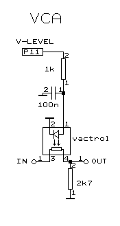
Using a vactrol as a VCA is very simple, here is the circuit:


The 1st circuit is all you need for ac-only input signals.
If you have input audio signals with a dc-component (offset or bias) use the 2nd circuit to prevent clicking.
Vactrol advantages are: no crosstalk from control signal, very low distortion,
very high signal level handling (40Vpp, if you limit LDR current).
Drawbacks are: rather large component size, shortest attacktime a few millisecond, controlcurve not exponential.
Decaytime is longer but that is "musically pleasing" because real-life instruments
do not have an abrupt stop (and acoustics gives a decay tail anyway).
Using a microcontroller with PWM-DAC the VCA control curve can be made exponential with a lookup table.
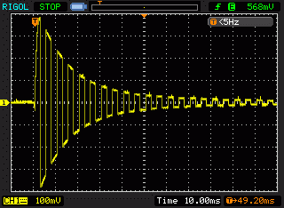
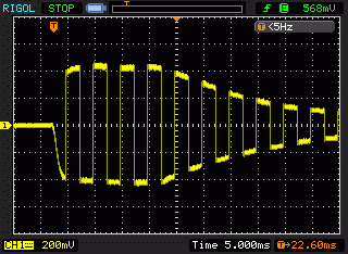
Here are a few scope pictures from a VCA vactrol that is controlled wit a pulse so that you can see the vactrol limited rise and fall times.
The load resistor does effect both rise and fall time in opposite way.I found that around 3kohm gives a short rise with an acceptible longer fall time.
The LDR resistor has a slow off response so the higher the load resistance the longer it takes to fade out.


Both have a square wave audio input signal, left is high freq, right is low freq input.
here is a faster timescale measurement (5ms-div) showing details of the attack curve

data sheet of vactrol available at Digikey, Farnell.
More text will be added here


