SubSub page: VCA diode based
designs starting from approx 1975
Introduction:
A passive circuit using only diodes and resistors is a very simple way to make a VCA. It has some drawbacks: distortion above 100mVpp, control signal crosstalk, a nonexp controlcurve.
The distortion problem is the reason to put it directly after the oscillator, before the LPF VCF (see MonoVoks1).
Doing this, the dynamic range constrains at the input will be small (fixed amplitude waveforms) and distortion is also filtered by the VCF.
Using a microcontroller with PWM-DAC the VCA control curve can be made exponential using a lookup table.
The first VCA circuit is used in the MonoVoks1 where the following VCF can handle only 100mVpp so that fits.
The diodes in this circuit (1n4148) should be seen as a variable, current controlled, resistor with Rdiode=25k/I[uA]
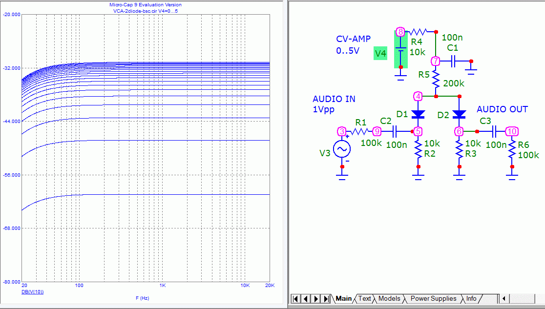
The circuit simulation model (SPICE, Microcap) below shows the behaviour, audio output while stepping controlvoltage.
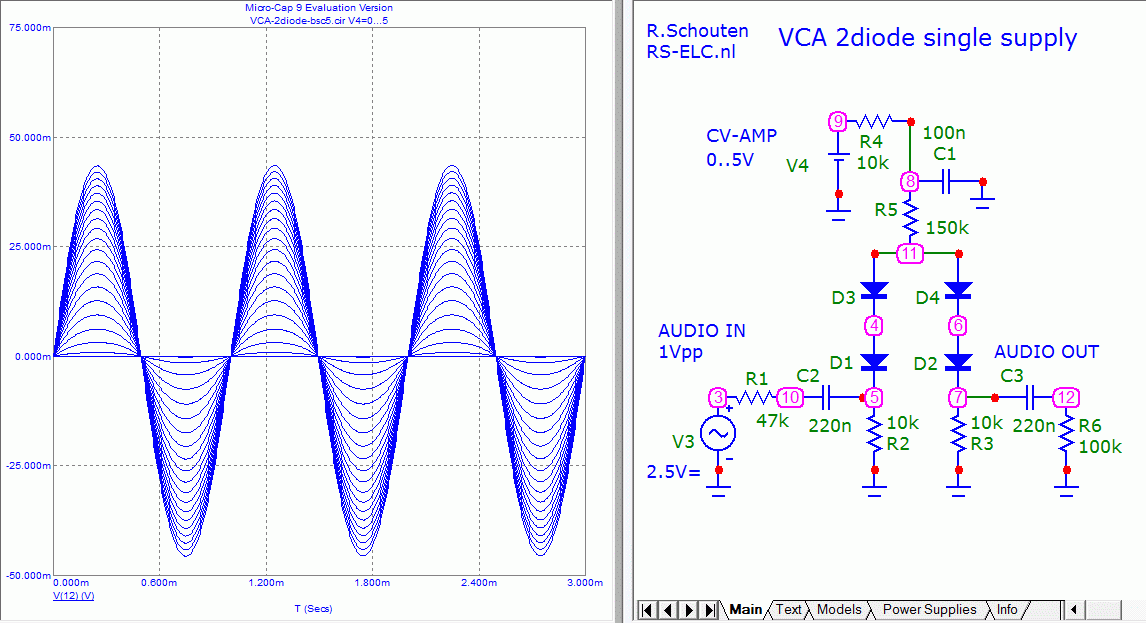
The simulation results as a "scope trace" sweeping the control voltage from 0 to 5V in steps of 0.25V:

Sending a increasing control current via V4 results in the diodes becoming more conducting and the audio signal being less attenuated.
The simulation results in the frequency domain, showing the controlcurve (dB vertical axis):

note that at 0V control the signal is off ( below -80dB, not shown in this graph )
Here you see that adding a diode allows for higher input signal levels before clipping (not build yet):
The simulation results as a "scope trace" sweeping the control voltage from 0 to 5V in steps of 0.25V:

Here you see that adding a transistor you can get an exponential control curve in dB/V (not build yet):
The simulation results in the frequency domain, clearly showing the controlcurve (dB axis):

note that this is not compensated for temperature drift.
More text will be added here


