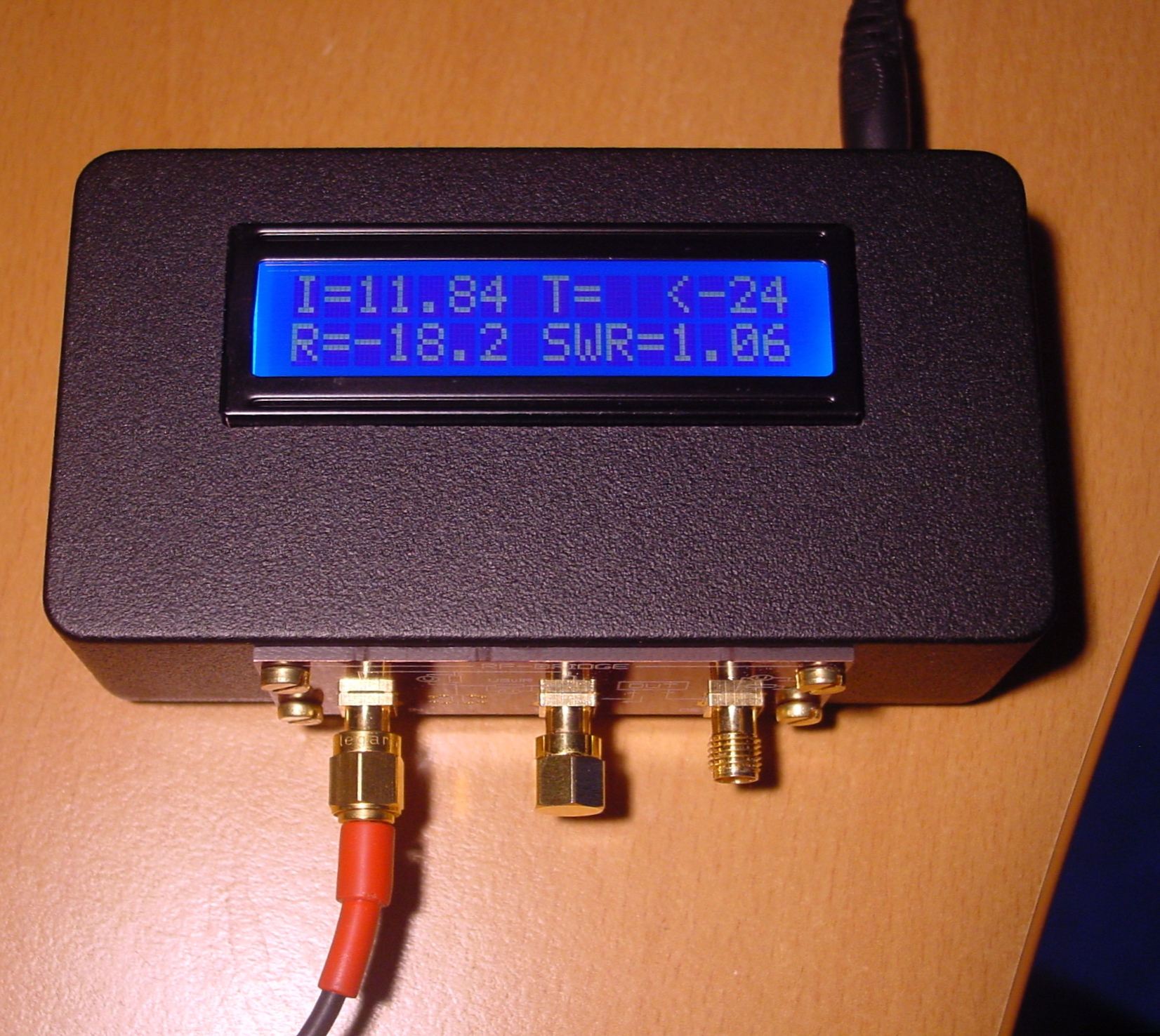
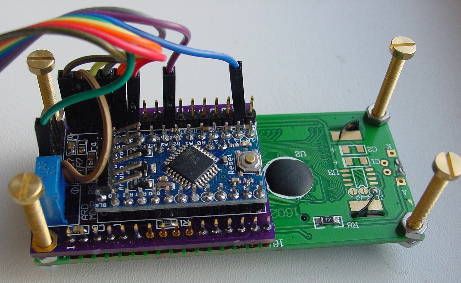
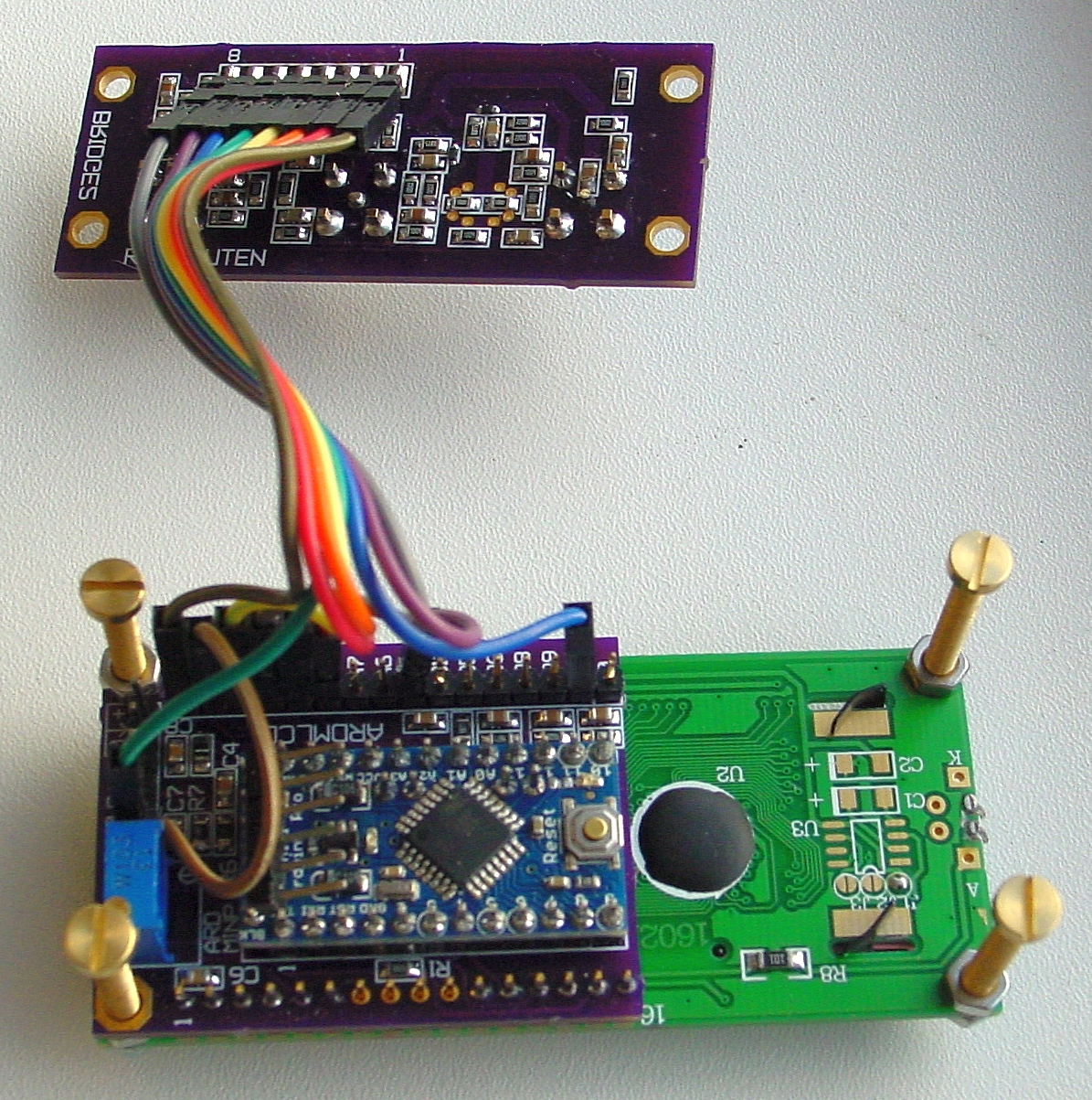
- Incident power.
- Reflected power
- Transmitted power
From this the VSWR/match/loss/gain is calculated (phase is not measured, only power)
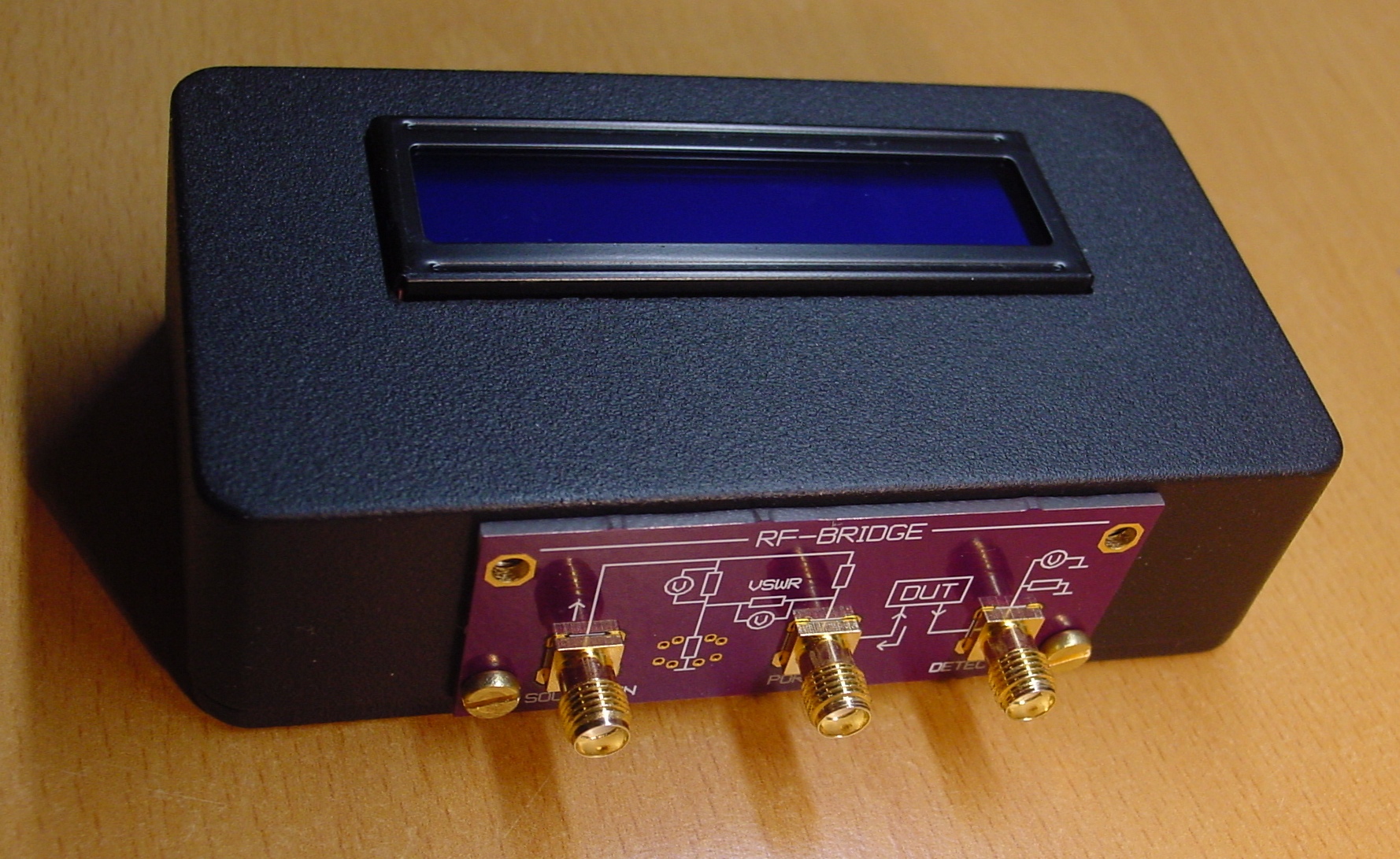
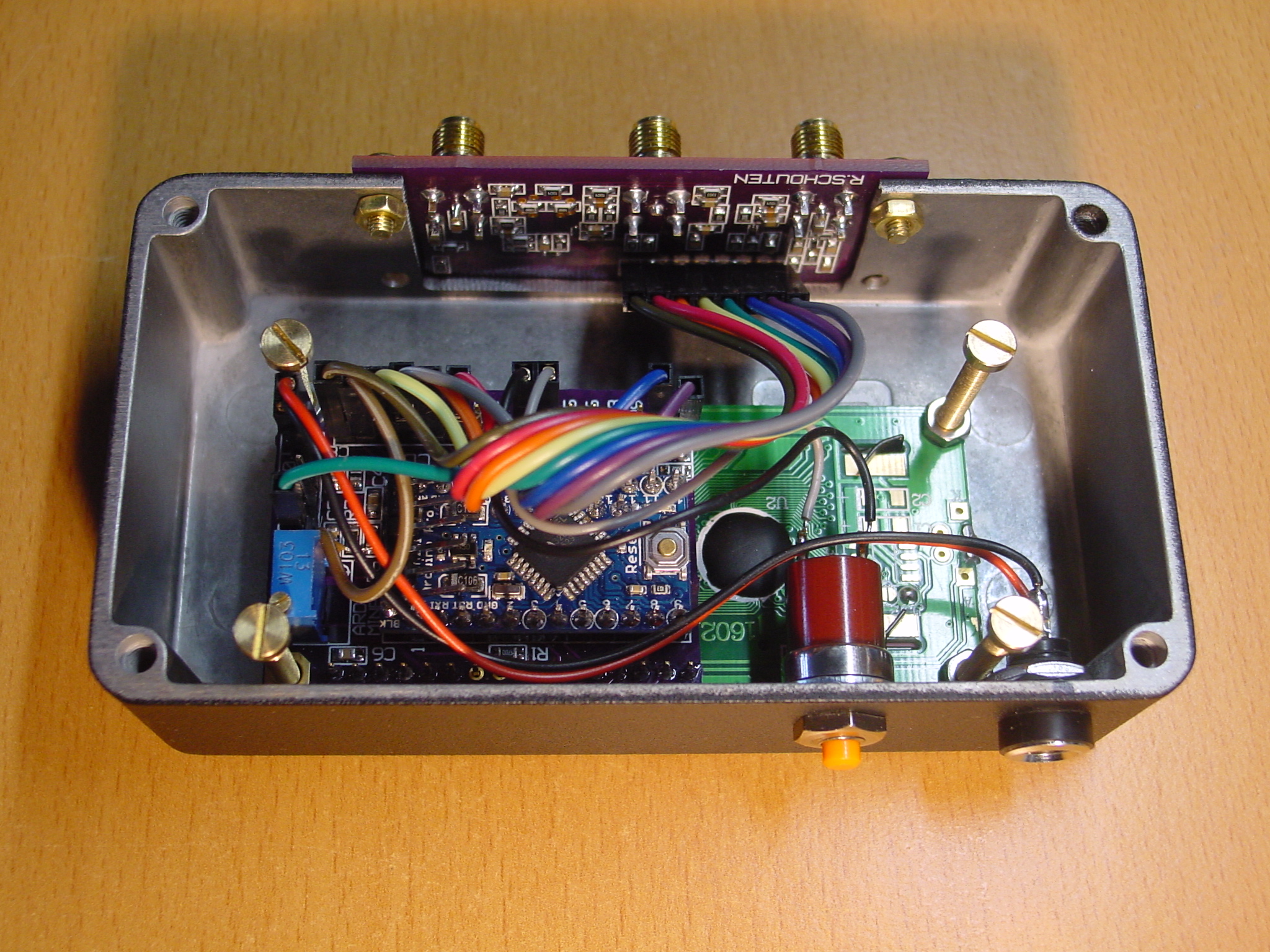
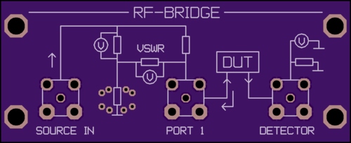
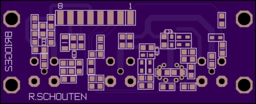
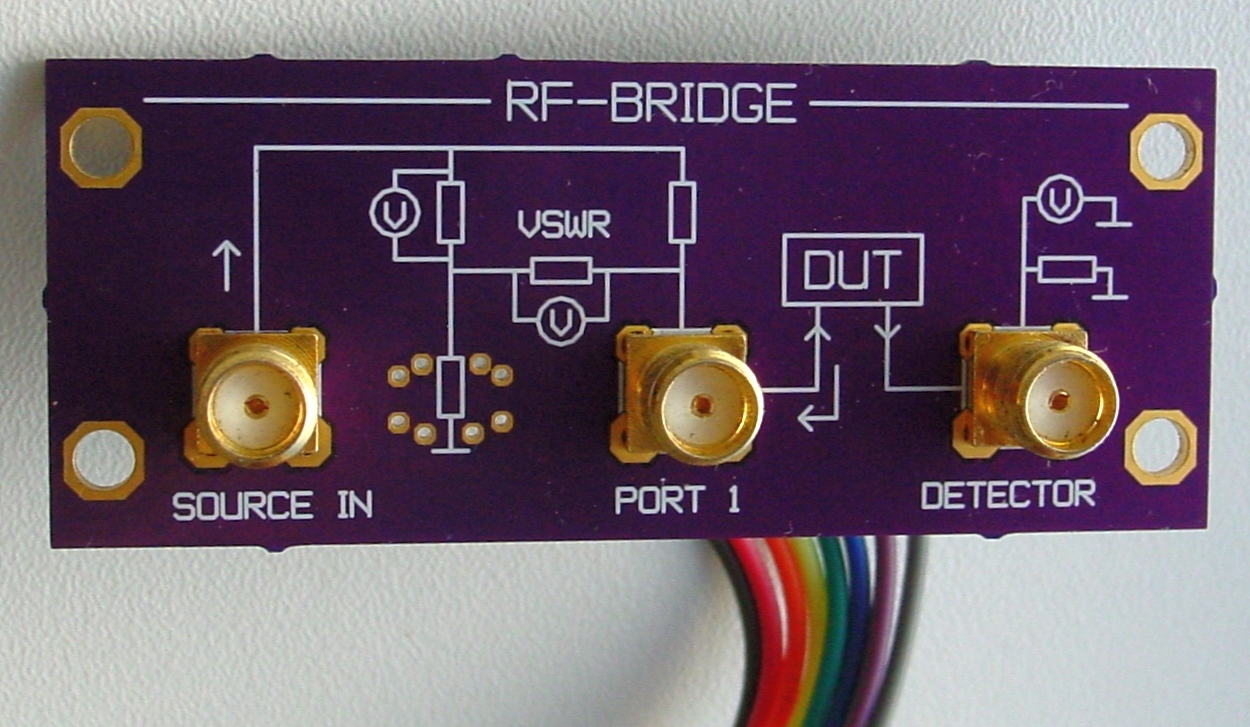
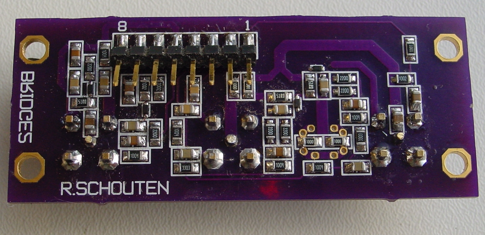
This is a very cheap resistive bridge with diode detectors (pcb with only resistors,capacitors,diodes: no chips)
Based on this paper from HP: page1
The basics of my circuit looks like this:
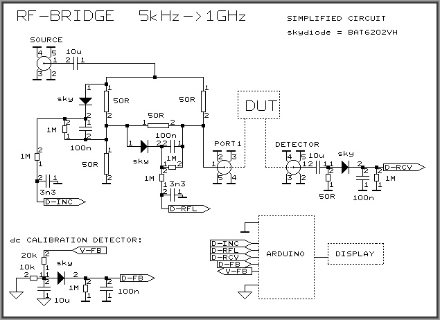
First I tested the diode detector circuit: diode-test
It turned out to have a flat response (within 0.2dB) up to 2GHz and offered some 40dB dynamic range.
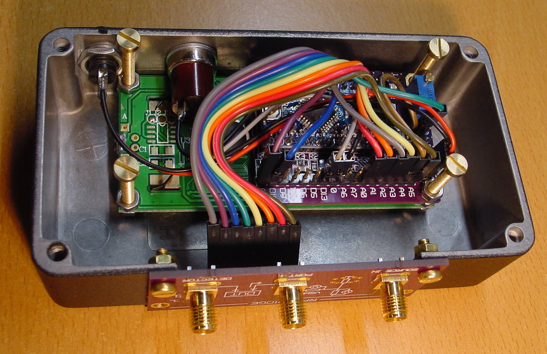
The added Arduino reads all the detectors, does the math and displays results on an LCD display (using a separate pcb). The bridge-pcb has an extra diodedetector circuit driven by the Arduino (PWM-DAC) to do auto-calibration.
When you connect a (50 ohm) generator to the source-input and a cable/filter/amp (DUT) between bridge-output and receiver, the display shows the incident,reflected, transmitted power and the calculated SWR.
When you connect a (50 ohm) generator to the source-input and a load to the bridge-output, the display shows the incident, reflected power and SWR.
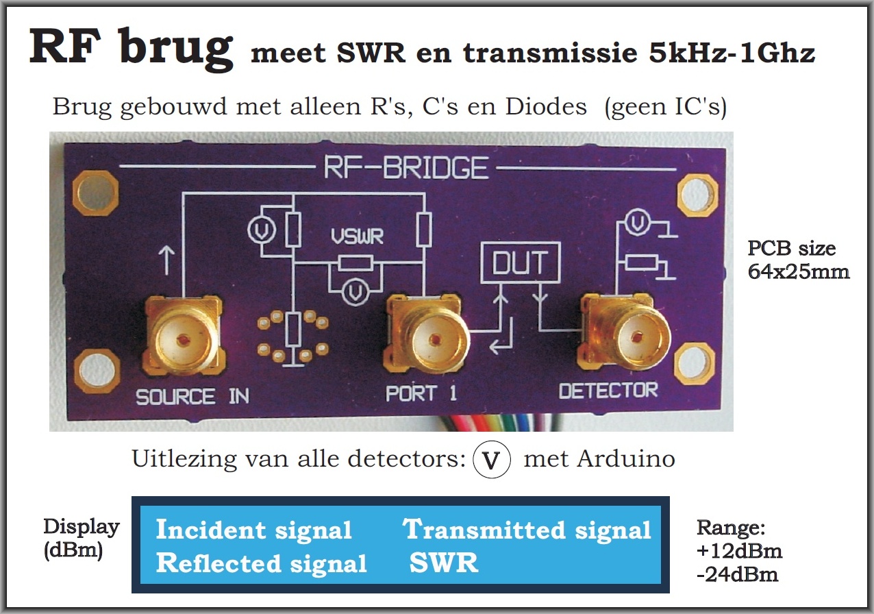
This project is not completely finished but it works, (hardware and software).
Measured functional bandwidth is 1kHz-1GHz (degrading specs <5kHz and >600Mhz)
receiver-detector (transmission) measured data:
Power range: +12...-24dBm
S11: <-30dB up to 500MHz and <-25dB up to 1GHz
Frequency response is flat within 0.2dB from 5kHz to 1.5GHz
Bridge data:(still under development)
directivity 30dB @10MHz 20dB@400MHz
S11: <-20dB up to 400MHz and <-13dB up to 1GHz
