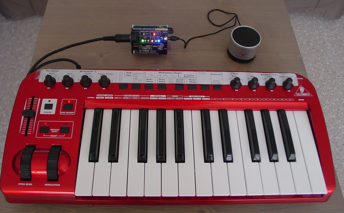
Monophonic synthesizer with analog signalpad (VCA,VCF) controlled and programmed via MIDI. The latest hardware version has 2 light sensors as controllers and an option to connect a control voltage (keyboard).
All sounds are created via only 16 midi controllers (potmeters) no menus, no samples. It has an oscillator with PWM and a Suboscillator that can do noisepatterns and formants.Two syncable modulators can act as Envelope Generator or LFO. In the LFO mode they have the possibility to apply patterns to their waveforms creating dynamic modulation sequences as can be heard in the example sounds.
The VCF circuit (HP/LP) is new but is inspired by the concept of the PoliVoks filter. Here it is simplified to using only one commonly available opamp.
The VCA is also kept simple, basically a circuit using 2 diodes.
Schematics and pcb will appear on this page but details on the circuit designs can be found at the page: Synthesizer circuits
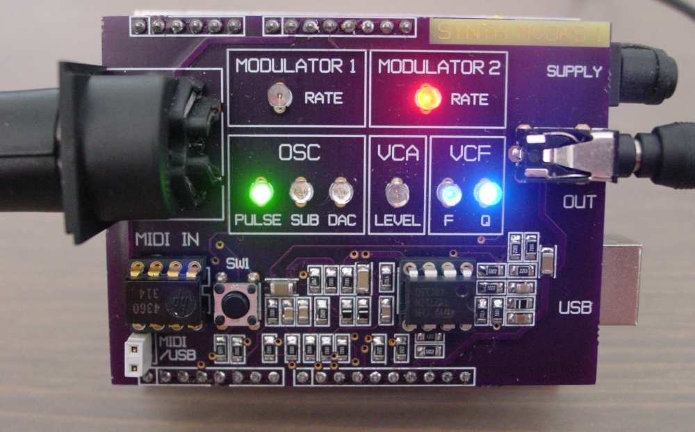
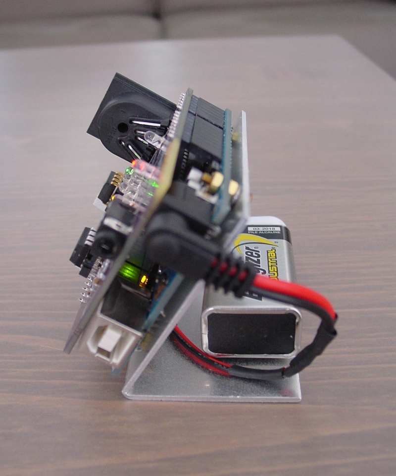
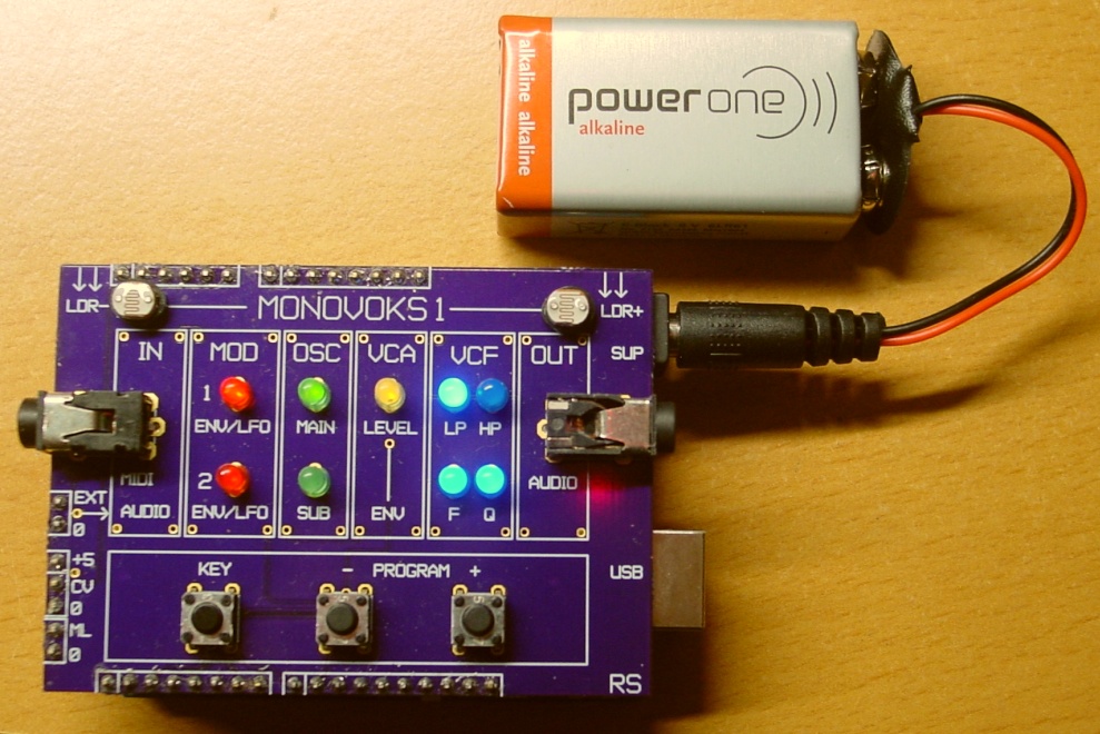
The 2-layer PCB is designed as an Arduino-UNO shield with most of the circuit mounted on the back. The prototype shown had quite some modifications, a redesign pcb with added functions was ready in november 2018. Added functions are: Audio input option for VCF, Light sensors for: control, note trigger and/or pitch. Keys to select programs and trigger note, control voltage (Kyb??) input option.
basic synth structure
(no effects, no sequencing, no multitrack)
sound1 changing filterQ, and going from LPF to HPF
sound2 1st LFO pulse, 2nd LFO randomstep on filter
sound3 classic synth
sound4 on the run
sound5 SubOsc droneTone
sound6 HighPass filter with resonance
sound7 Wavestation ambient
sound8 voice
sound9 SubOsc on fixed tone
sound10 LFO doing pitchpattern arpeggio
sound11 fuzzed wavepatternsequence
sound12 steps in wavesequencing
Nice fuzzgitar sounds:using formantmode on SubOsc
sound13 fuzzgitar1
sound14 doomsday gitar
sound15 superfuzz gitar
sound16 fuzzgitar2
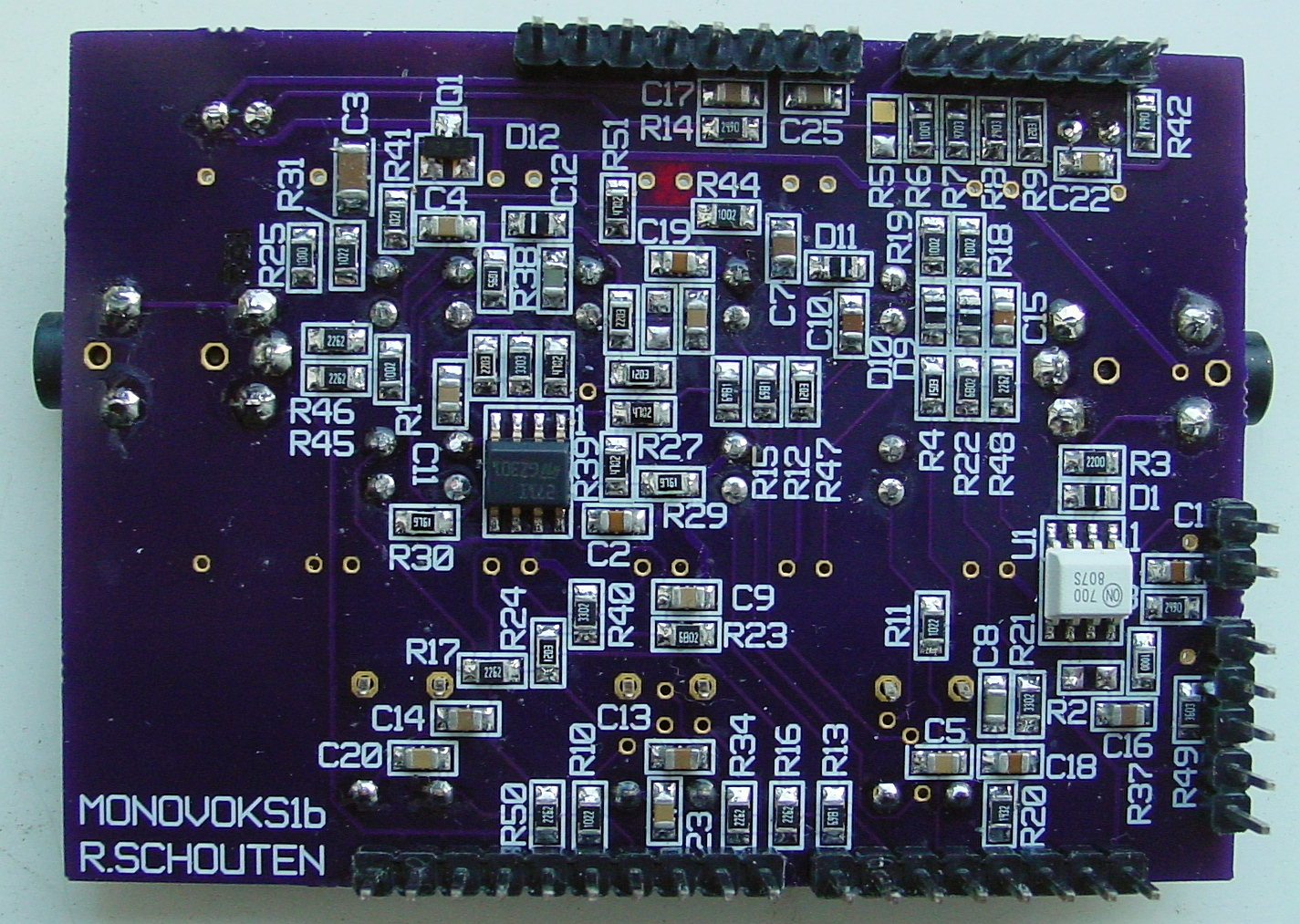
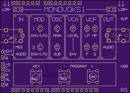
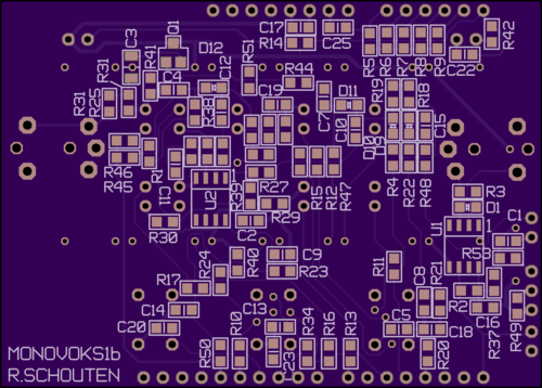
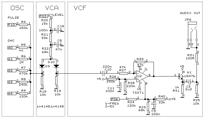
Oscillator and DAC come from Arduino-UNO. Labels (for example P10) indicates Arduino pin numbers. Oscillator is made with build-in timer/counter. Pulse and PWM waves comes directly from counter (P10). Other signals are made with R-DAC (A0-A4 used as outputs).
The VCA is using 2 diodes as variable resistors, current controlled via PWM-DAC from P03.
The VCF is based on a biascontrolled opamp, frequency is set via PWM-DAC from P06.
In this simplified circuit you can recognise the LowPassfilter explained on the synthesizer circuit pages. The VCF circuit is not fully drawn yet, we will add the other elements in the next slides.
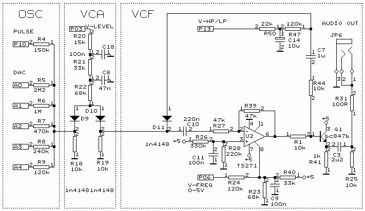
The VCF shown on slide1 is a lowpass filter (inverting). If we now sum an equal portion of the input to the output we subtract the two and get a highpass filter. If we do this with an electronic switch we can select High/Low pass.
Diode D11 is the switch that gets a dc-current via P13=high if the highpass is selected. To prevent audible clicks, a large RC time is added to P13.
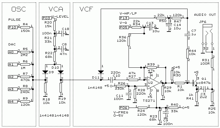
The VCF also needs a control for the amount of peaking (Q).
We start by adding load resistors (R29,R30) and a variable output dc level to make use of the asymmetry of the TS271 opamp output stage.
To prevent audible clicks, a large RC time is added to P05.
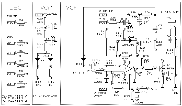
To reach higher levels of peaking (Q) two feedback tricks are used:
1-at higher V-Q settings the diode D12 will be forward biased and forms a decreasing resistance. This way the opamp loopgain is increased (the circuit gain is lowered) and the opamp shows more peaking at the cutoff frequency.
2-An extra RC (R38-C4) is now in the loop, causing more phaseshift. Increasing C4 can make it even oscillate.
circuit diagram version 1b3
pcb gerber files version 1b
pcb component placing
Arduino Uno code version 09z
component list
pushbutton switch
3.5mm connectors
MIDI connector pinning